Heated room
In this example, a room which is heated by an HVAC system is considered. The FMU is used to set the massflow rate and temperature of the hot air blown into the room to raise the temperature.
The schematic of the FMU is shown in the following figure.
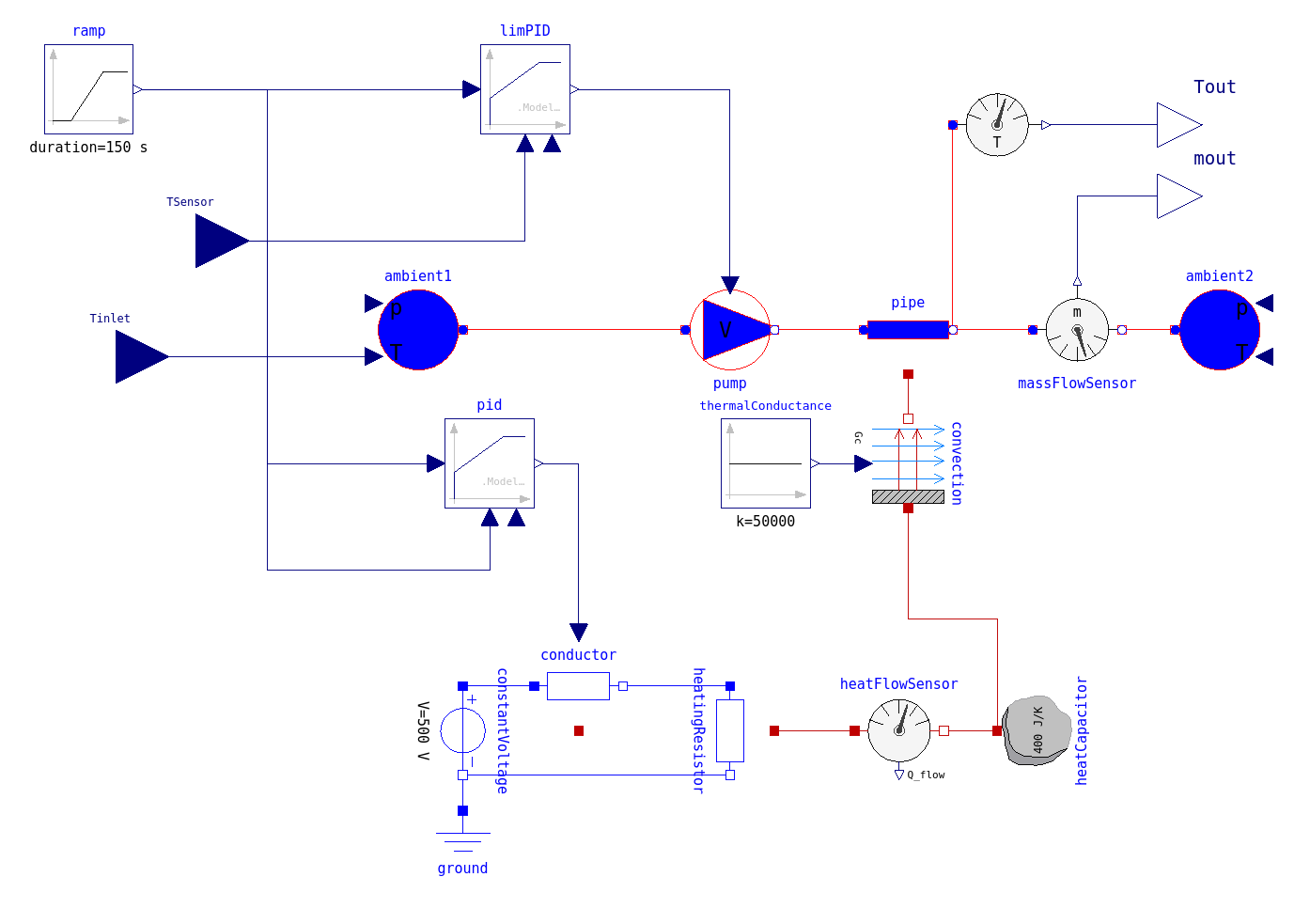
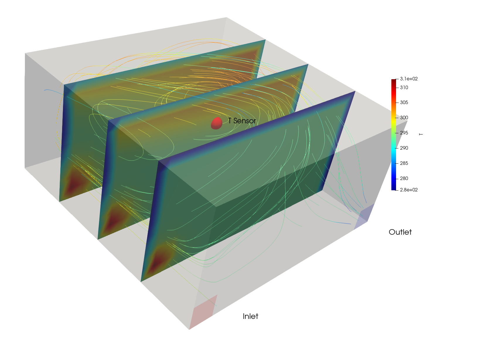
Here, air is sucked in at one corner of the room, is heated by convection in a heat exchanger and is then exhausted at another corner of the room. The FMU controles the Pump and Heater by taking the measured room temperature in the middle of the room and the inlet temperature as inputs and sets the pump speed and heating power according to a pre defined temperature ramp. The temperature increase is given by a linear function within the ramp block. One PID regulator sets the control value for the pump using the measured temperature in the middle of the room. Another PID regulator sets the control value of the heater power. The heated air is then expelled at the outlet patch by passing the temperature and the massflow rate to the OpenFoam solver to solve for the temperature and flow field inside the room as shown in the following figure.
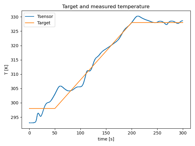
The temperature of the room taken at the middle of the room by a temperature probe along with the target temperature set by the ramp, are shown in the figure below.
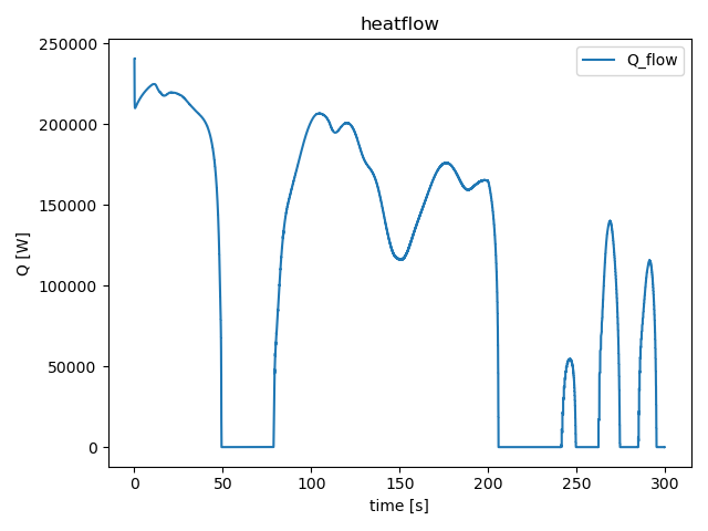
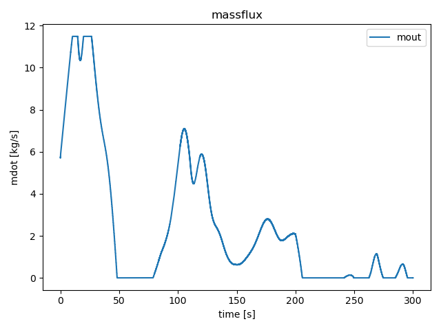
The heat flux and mass flow rate of the heater are depicted in the next two figures.